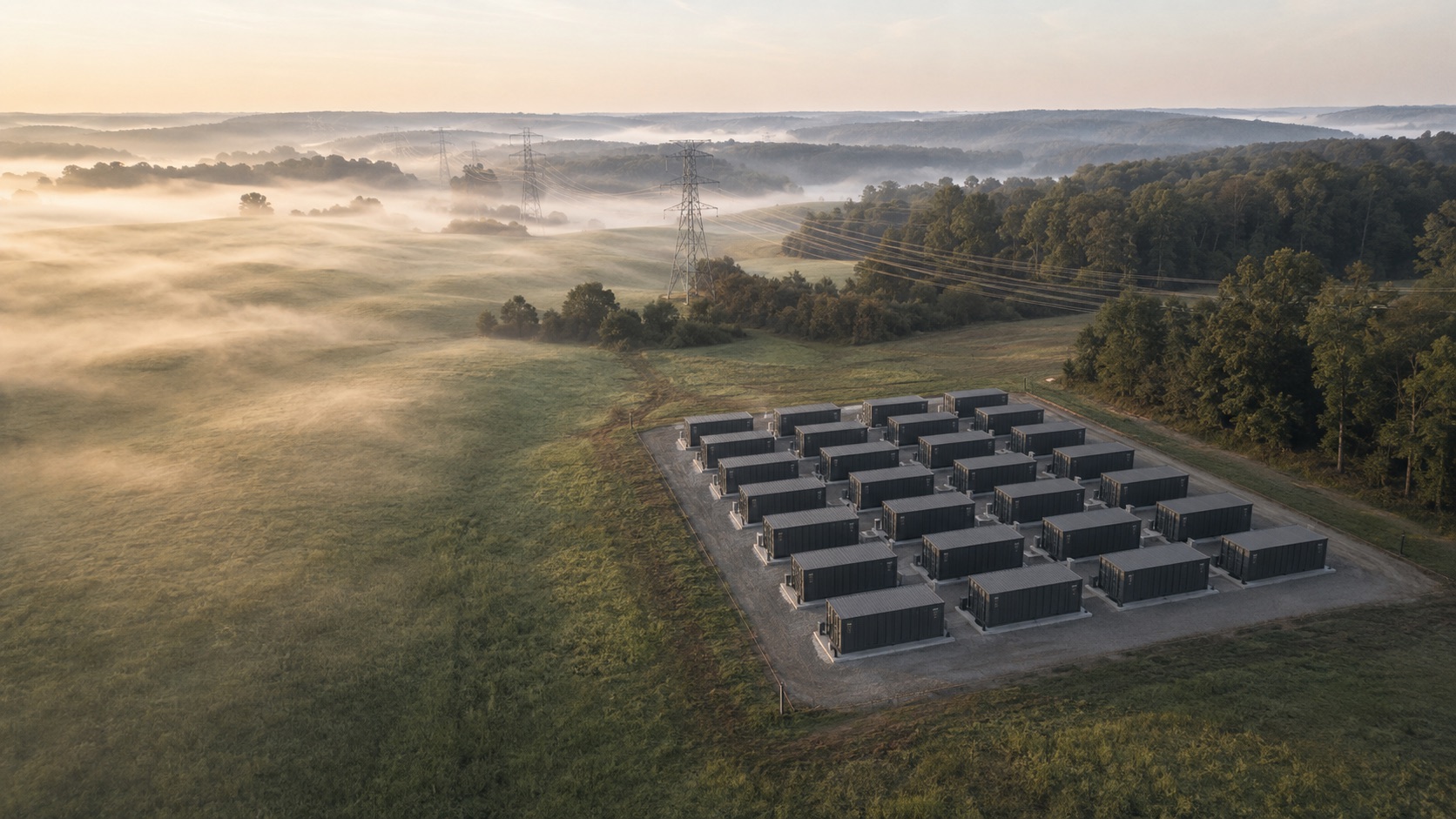
Energy module
Medium and low voltage interface, transformers, UPS, A/B distribution, batteries, and generator interfaces.
High-density AI infrastructure
Twenty-four rack positions, warm-water direct liquid cooling, integrated power and heat rejection. Electrical, thermal, control, fire, and monitoring systems are tested together before the modules ship.
Integrated system architecture
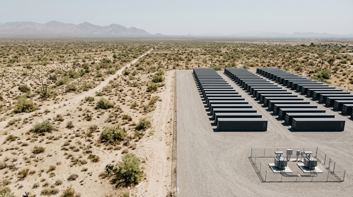
The platform separates power, IT, and facility functions into modules that are built and tested in a factory. Those three, with the external heat rejection plant, make one 2.5 MW unit under one coordinated power and thermal architecture. The arrangement repeats from site to site, so each project integrates against the same utility, generator, network, and water interfaces.
Medium and low voltage interface, transformers, UPS, A/B distribution, batteries, and generator interfaces.
24 rack positions, high-density busway, rack liquid interfaces, residual air cooling, and technical access.
Pumps, filtration, controls, air-side cooling, fire protection, and building management and monitoring interfaces.
The plant sits outside the modules at 2.50 MW duty. Dry operation is the normal mode, with tank-fed adiabatic assist when the climate calls for it.
Built for high-density AI
Thermal management
Warm water at 41/51 °C carries the GPU heat. A small air-side system takes the rest. Heat rejection runs dry until roughly 39 °C ambient, then draws on a tank, so nothing has to be plumbed to a utility.
Reference technical configuration
Values below are the current engineering reference for the GB300 configuration. Rack interfaces, secondary loop conditions, and the certification path follow the rack OEM selected for the project.
| GB300 NVL72 rack positions | 16 |
|---|---|
| Network and support rack positions | 8 |
| GPUs, reference configuration | 1,152 |
| Grace CPUs, reference configuration | 576 |
| Modeled rack power, GB300 EDPp | ≈155 kW |
| Modeled electrical peak, IT | 2.536 MW |
|---|---|
| Reference gross facility interface | ≈3.0 MW |
| Busway provisioning per GB300 rack | 192 kW |
| Distribution basis | Independent A/B paths; optional 2N UPS |
| UPS autonomy, budgetary basis | 15 minutes |
| Direct liquid cooling design capacity | 2.100 MW |
|---|---|
| Air-side design capacity | 0.280 MW |
| Total thermal design basis | 2.380 MW |
| Heat rejection duty capacity | 2.500 MW |
| Facility water supply and return | 41/51 °C |
| Normal operating mode | Dry, no water |
|---|---|
| Adiabatic transition reference | ≈39 °C ambient |
| Utility water connection | Not required |
| On-site storage equivalent | 100 m³ |
| IT module envelope | 16.2 m × 6.8 m |
Flow rates, rack-level thermal load, busway installed capability and module zoning are in the technical brief.
Deployment
Load, utility service, water availability, and site climate against the unit footprint.
Rack geometry, lifting routes, liquid feed, cable entry, and clearances are fixed after OEM selection and transport review.
Mechanical and electrical systems are integrated and functionally tested before shipment.
Modules are set, then connected to utility, generator, network, and water interfaces.
Site acceptance testing, then handover against the project commissioning scope.
Scale
One unit
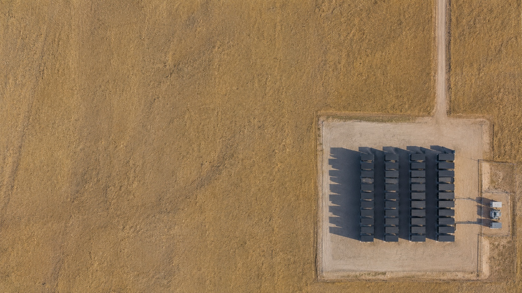
Three modules and one heat rejection plant on a single prepared pad.
Phased site
Each unit repeats the same power and thermal architecture, so later phases integrate the same way as the first.
Campus
Utility, generator, network, and water interfaces stay consistent as the site grows.
Engineering basis
The unit is engineered around high-density GB300 NVL72 deployment requirements. Final power interfaces, rack CDU implementation, network fabric, and certification requirements are coordinated with the selected OEM during detailed engineering.
The platform supports concurrently maintainable, Tier III-equivalent project objectives, subject to the final project redundancy matrix, utility demarcation, and certification scope. Installed feeder capability is a design and protection value and is not a figure for simultaneous IT consumption.
Check equipment lead times →Send the capacity you need, whether that figure is IT load or facility load, and the quarter it has to be live. We come back with scope and schedule.